
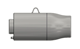
Series 3500 IS In-line Seismic Expansion Joints combine the axial motion capability and safety of Series 3500 Externally Pressurized Expansions with the universal motion capability and reliability of Hyspan Barco Ball Joints to provide in-line axial and lateral movements of +/- 6”, +/- 12”, +/-18” or +/- 24”. This rugged reliable product provides seismic isolation of piping without a change in direction or the addition of pipe length.
3501SRV-3502SRV Safety Relief Valve 3 Ply Ext. Pres. Vent Exp. Joint
Information at a Glance
Series
3500 Ext Pres Bellows Expansion Joints
Material
Steel
Size
2-240 in. / 50-6000 mm
Pressure
≤150 & 300 PSI / 10 & 20 Bar
Motion
16+ in. / 400+ mm
Canadian Registration
![]()
This product is registered throughout Canada under
CRN 0D9278.59870YTNADD3
Other Products
Product Description
Technology & Advantages
The rugged in-line construction of the Series 3500 IS seismic expansion joint provides a reliable heavy-duty solution to absorb large multi-plane seismic motions. Designed specifically to connect the piping of two structures that move independently in a seismic event. The design does not require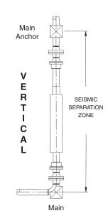
a change in piping direction and therefore does not add elbows and other components that increase
pressure drop and heat loss. The envelope is minimum to facilitate installations in tight fitting areas
and retrofitting of existing piping installations.
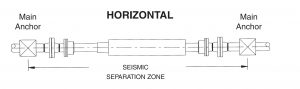
Series 3500 IS expansion joints combine the design techniques of two well established Hyspan products; Hyspan Barco Ball Joints provide lateral offset and rotation, and Hyspan Series 3500 externally pressurized expansion joints provide axial extension or compression. The bellows is enclosed and all component parts are made from standard pipe or equivalent. The installation can be horizontal or vertical as illustrated.
Common Applications
Series 3500 IS seismic expansion joints must be installed between two anchor points that are designed to react to the pressure thrust and bellows spring force of the axial expansion joint, and the lateral force resulting from the flex torque of the ball joints. The maximum lateral force on the anchor is equal to the break away force which is tabulated in Column 5 of Table 1 for the standard designs. After break away, the force is reduced, and it is not a function of pressure. The maximum axial force is a combination of the pressure thrust force which is tabulated in Table 2, Pressure and Force Data, and the Axial Spring Rate that is tabulated in Column 4 of Table 1 multiplied by the axial deflection.


Design Data
Linear thermal expansion of pipe per 100 feet between 70° and the tabulated temperature


Note:
(1) The values listed are the center to center distance measured in feet.
(2) Pipe guide spacing is a function of the expansion joint spring rate and effective area. The tabulated values are for Series
3500 expansion joints at the system design pressure listed.
(3) The pressures listed are design values. Guide spacing has been calculated for the test pressure (1.5 X design).
(4) Refer to Catalog 1004 for complete details on Hyspan Series 9500 Pipe Guides and their application.

Design Pressure: 150 psig Test Pressure: 225 psig Design Temperature: 500°F

Design Pressure: 150 psig Test Pressure: 225 psig Design Temperature: 500°F

Design Pressure: 300 psig Test Pressure: 450 psig Design Temperature: 500°F

Design Pressure: 300 psig Test Pressure: 450 psig Design: Temperature 500°F

Note:
(1) Force per inch of compression resulting from the bellows spring constant. Refer to Table 2 for pressure thrust force.
(2) For Type 3505 and 3506 travel stated is the total. Travel each side of the anchor is 1/2 the tabulated value.
(3) Refer to Table 4 for housing outside diameter, drain port size and anchor base details and centerline height of anchor
base models.
Design Pressure: 150 psig Test Pressure: 225 psig Design Temperature: 500°F

Design Pressure: 300 psig Test Pressure: 450 psig Design: Temperature 500°F

Note:
(1) Force (lbs.) per inch of compression (pipe expansion) resulting from bellows spring constant.
(2) Refer to Table 4 on Page 7 for housing outside diameter and drain port size.
(3) Refer to Applications on page 4 for correct installation.
(4) The anchor force is calculated as follows:
Anchor Force (lbs.) = Spring Rate
Ordering Information
- Refer to Tables 5 through 10 to select the configuration and service conditions required for your application.
- If the travel required is unknown, see the method of calculation on Page 5 (of the full catalog).
Example
Single Expansion Joint Steel pipe weld ends 150 psig at 500°F maximum 4.0″ axial travel maximum 2″ NPS
3502-131-4
3502: Type specification, steel pipe weld end both ends, steel housing and guides
131: Size & pressure designation, 2″ NPS, 150 PSIG
4: Axial travel, 4.0″ compression, 1.0″ extension
- Single expansion joints, 3501 and 3502, ordered with anchor based are identified as 3501AB and 3502AB.
- Anchor bases are standard on dual anchor base joints, 3505 and 3506, and do not require the AB suffix.
- In-line pressure balanced joints are available as single configurations and identified as 3501PB and 3502PB—refer to In-Line Pressure Balanced Expansion Joints.
Hyspan products are available from Sales Representatives and Distributors, or they can be purchased direct from the factory. The minimum factory order for open account customers, COD shipments, or bank card sales is $100.00 (USD). All major credit or debit cards are accepted. The minimum order for new account applicants is $100.00. Our Confidential Credit Application can be downloaded and forwarded to Hyspan for processing. All orders are subject to the following Terms and Conditions, and the following warranty applies to all material. Please read these documents.
Many Hyspan products have an extended warranty. Refer to individual products for the applicable warranty. Unless otherwise stated this Limited Warranty applies to Hyspan products.
![]() Confidential Credit Application (13.9 KB), can be completed on line.
Confidential Credit Application (13.9 KB), can be completed on line.
