Sample Product Item
Information at a Glance
Series
3500 Ext Pres Laminated
System Technology
Industries
Material
Steel
Size
2-240 in. / 50-6000 mm
Pressure
≤150 & 300 PSI / 10 & 20 Bar
Motion
16+ in. / 400+ mm
Canadian Registration
![]()
This product is registered throughout Canada under
CRN 0D9278.59870YTNADD3
Other Products
- 3501-3506 Single & Dual 3 Ply Ext. Pres. Expansion Joints
Product Description
Series 3500 Externally Pressurized Expansion Joints are designed for installations where the principal movement is axial.
- Standard single and dual designs are available 2” through 24” NPS with 4” through 16” axial compression.
- Service conditions are 150 and 300 psig to 500°F. Welded and flanged end connections are standard, with grooved ends optional.
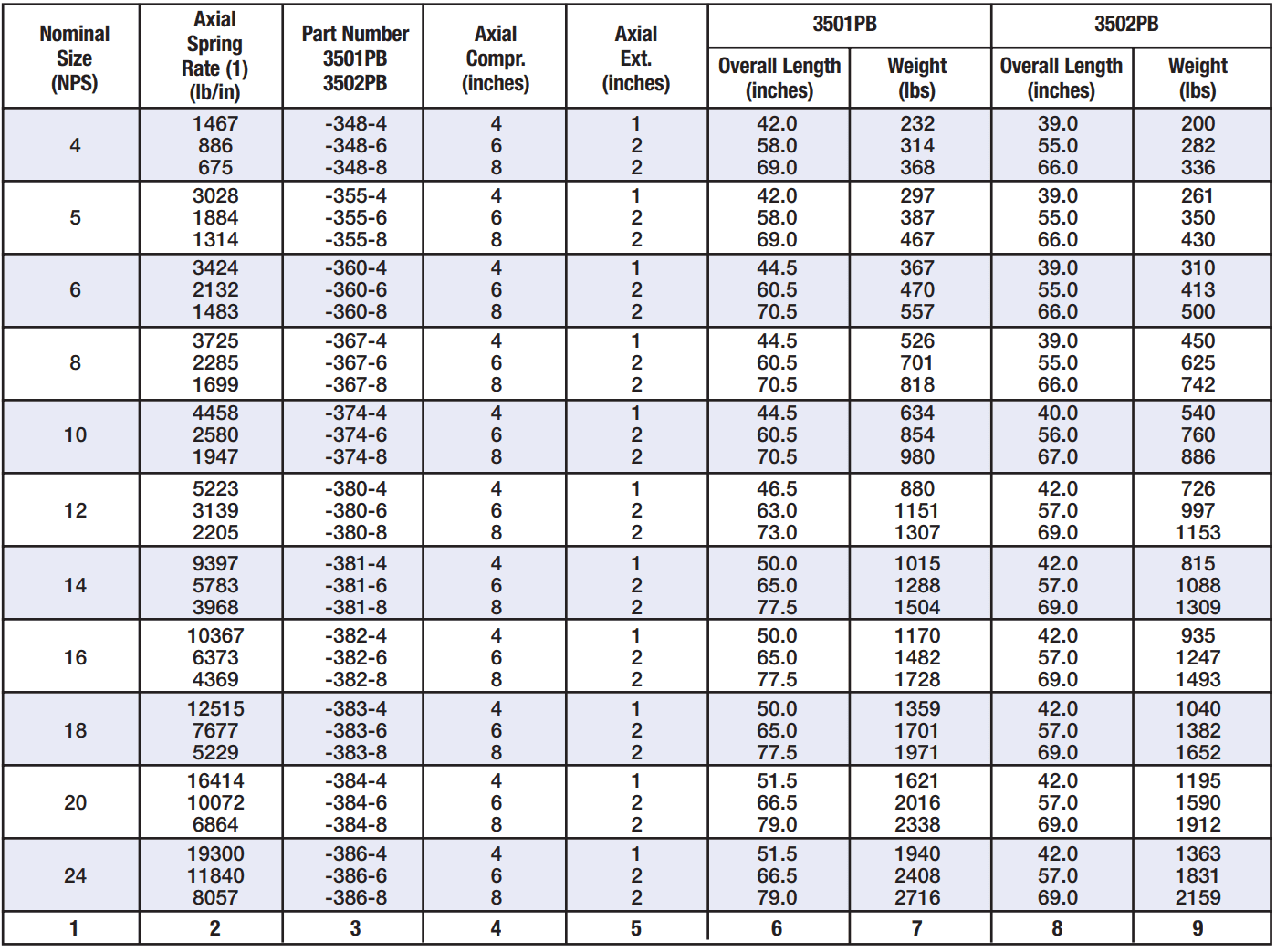
Standard in-line pressure balanced configurations are available 2” through 24” NPS with 4”, 6” & 8” axial travel rated for 150 & 300 psig to 500°F.
Technology & Advantages
- 3-Ply Laminated Bellows for maximum flexibility and minimum spring force in the shortest length
- Very Small Effective Area to Minimize Operating & Test Pressure Force
- Stainless-to-Stainless Bellows to Collar Welds for maximum corrosion resistance at the bellows attachment
- Internal Venting for faster filling and draining, and increased system safety with quick pressure changes
- Over Compression Safety Allowance of 0.5″
- Standard Drain and Plug for System Drainage
- 5-Year Warranty
- The bellows element of Series 3500 Expansion Joints is completely enclosed and externally pressurized
- This prevents damage to the bellows and eliminates pressure instability.
- The pipe telescopes into the expansion joint protecting the bellows and providing a smooth full bore interior.
Series 3500 products are available from stock and have a five year full replacement warranty.
Type 3502 Cutaway

Common Applications
- Series 3500 expansion joints are designed for
- properly maintained steam, hot water and chilled water systems.
- other media that are compatible with the following materials of construction used in these expansion joints
- Flanges
- Pipe
- Guide Rings
- Drain Port & Plug
- Bellows
(For further details on the materials used for standard construction refer to Materials of Construction & Dimensional Data.)
- Be certain that the exterior of the expansion joint is not exposed to corrosive substances such as minerals in ground water and road salt.
Design Data
Note:
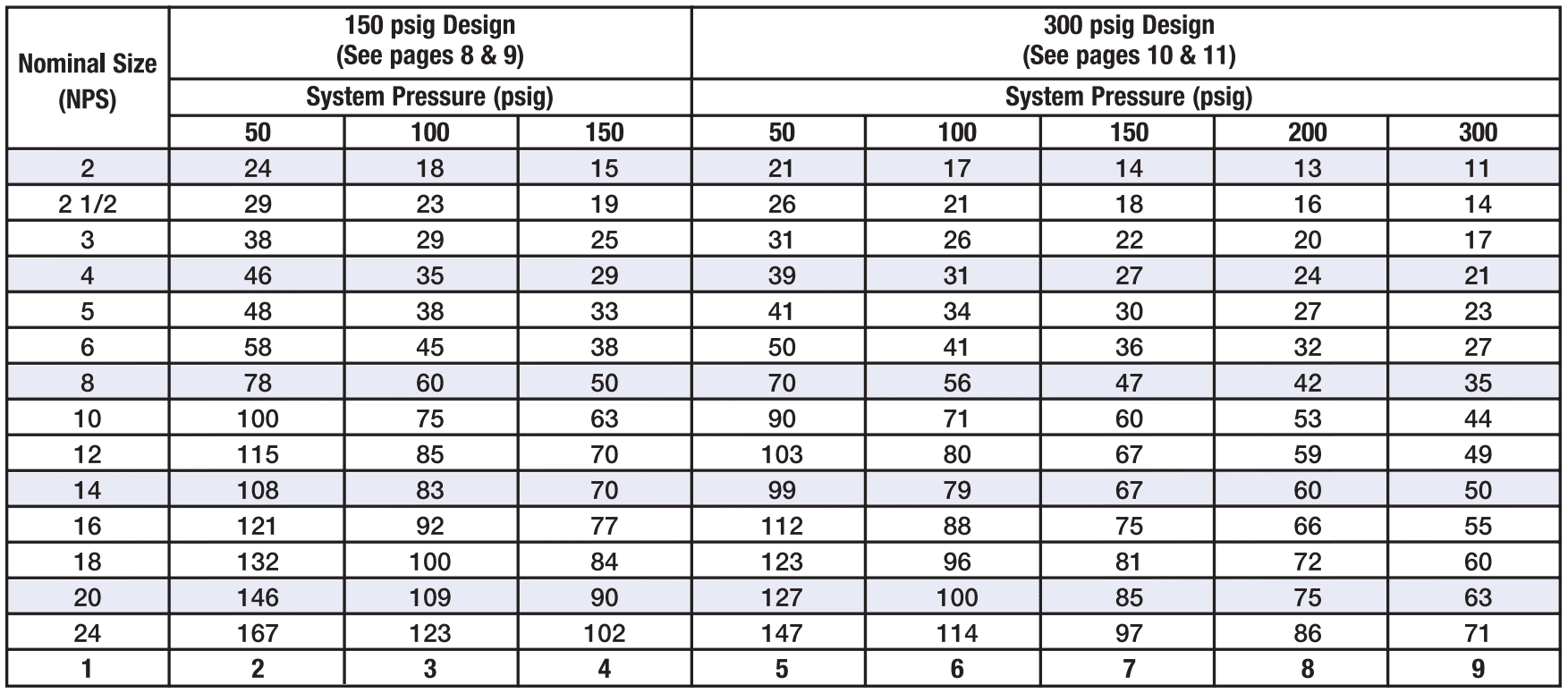
(1) The values listed are the center to center distance measured in feet.
(2) Pipe guide spacing is a function of the expansion joint spring rate and effective area. The tabulated values are for Series
3500 expansion joints at the system design pressure listed.
(3) The pressures listed are design values. Guide spacing has been calculated for the test pressure (1.5 X design).
(4) Refer to Catalog 1004 for complete details on Hyspan Series 9500 Pipe Guides and their application.
Design Pressure: 300 psig Test Pressure: 450 psig Design: Temperature 500°F
Note:
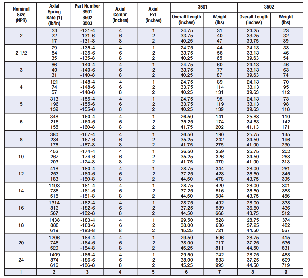
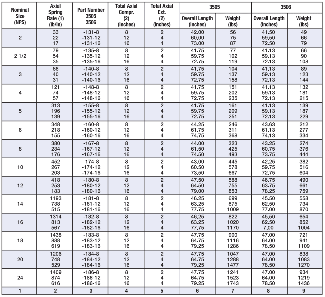
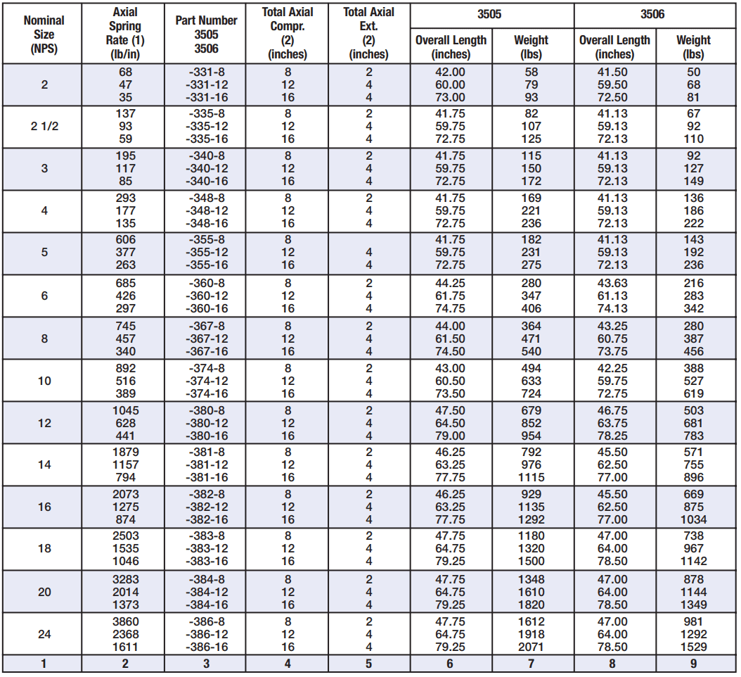
(1) Force per inch of compression resulting from the bellows spring constant. Refer to Table 2 for pressure thrust force.
(2) For Type 3505 and 3506 travel stated is the total. Travel each side of the anchor is 1/2 the tabulated value.
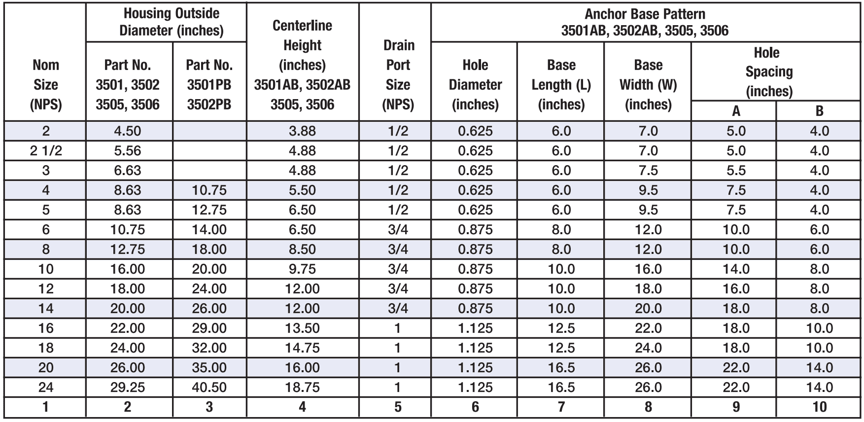
(3) Refer to Table 4 for housing outside diameter, drain port size and anchor base details and centerline height of anchor
base models.
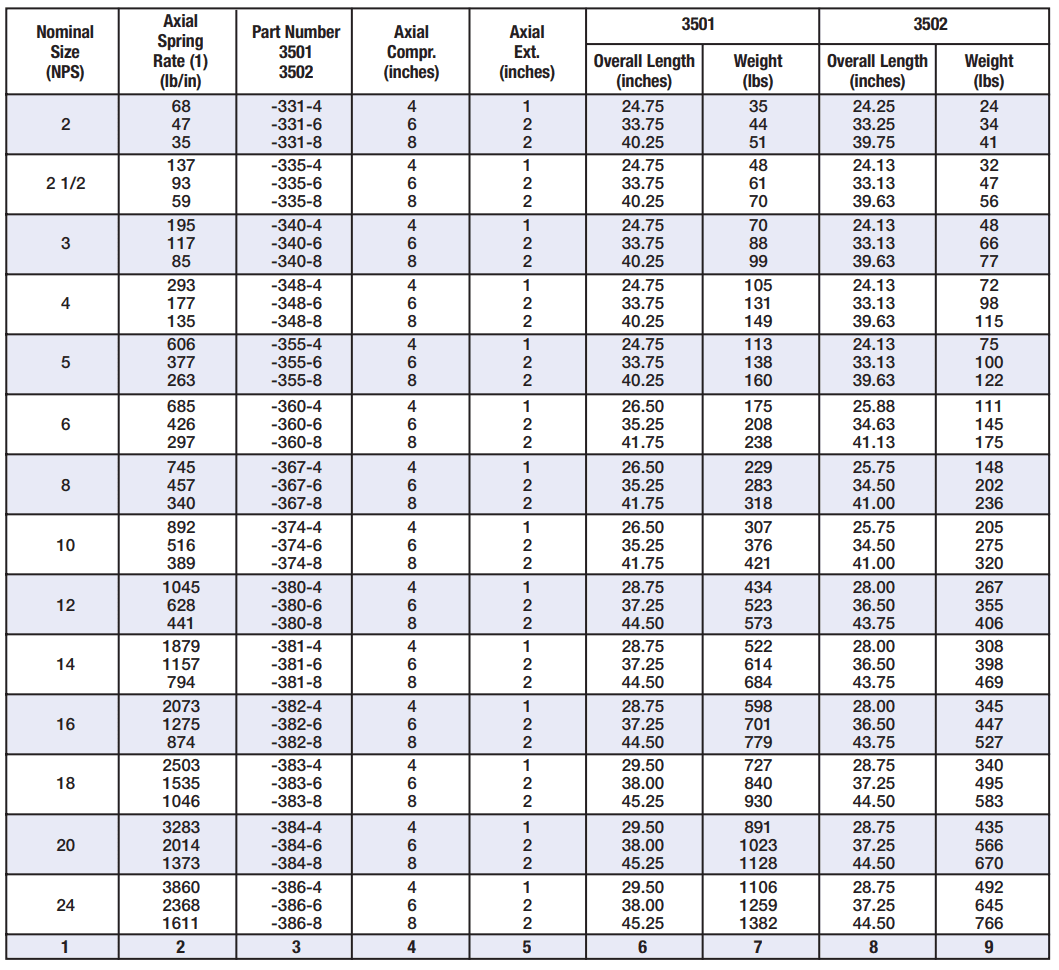
Design Pressure: 300 psig Test Pressure: 450 psig Design: Temperature 500°F
Note:
(1) Force (lbs.) per inch of compression (pipe expansion) resulting from bellows spring constant.
(2) Refer to Table 4 on Page 7 for housing outside diameter and drain port size.
(3) Refer to Applications on page 4 for correct installation.
(4) The anchor force is calculated as follows:
Anchor Force (lbs.) = Spring Rate
Ordering Information
- Refer to Tables 5 through 10 to select the configuration and service conditions required for your application.
- If the travel required is unknown, see the method of calculation on Page 5 (of the full catalog).
Example
Single Expansion Joint Steel pipe weld ends 150 psig at 500°F maximum 4.0″ axial travel maximum 2″ NPS
3502-131-4
3502: Type specification, steel pipe weld end both ends, steel housing and guides
131: Size & pressure designation, 2″ NPS, 150 PSIG
4: Axial travel, 4.0″ compression, 1.0″ extension
- Single expansion joints, 3501 and 3502, ordered with anchor based are identified as 3501AB and 3502AB.
- Anchor bases are standard on dual anchor base joints, 3505 and 3506, and do not require the AB suffix.
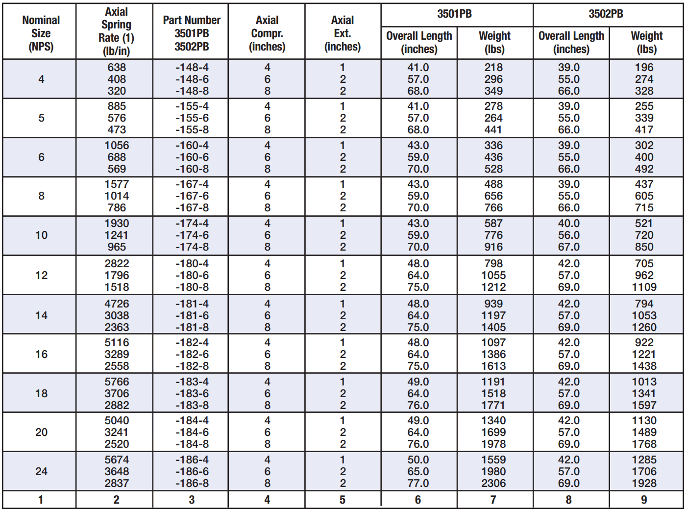
- In-line pressure balanced joints are available as single configurations and identified as 3501PB and 3502PB—refer to In-Line Pressure Balanced Expansion Joints.
Frequently Asked Questions
Lorem ipsum dolor sit amet, consectetur adipiscing elit?
Nulla a vehicula lectus. Vestibulum ante ipsum primis in faucibus orci luctus et ultrices posuere cubilia
Aliquam vehicula mollis est ut efficitur. Phasellus non lacinia mi, id tempor ante?
Fusce dignissim maximus nunc, eu porta lacus sagittis a. Donec venenatis diam at nibh volutpat consectetur. Nullam purus massa, molestie ut ipsum non, tempus cursus tortor. Cras tempor pretium imperdiet. Integer dapibus semper ante, et molestie leo semper vel. Nam suscipit sem sed ligula pulvinar,
Pellentesque nec blandit diam?
Phasellus sit amet sollicitudin mi, ut porta eros.
Downloads
General Downloads
- Catalog
- Approval Submittal
- Specifications
- Installation Instructions
- Warranty


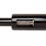 3501PB-3502PB Single 3 Ply Pressure Balanced Ext. Pres. Expansion Joints