
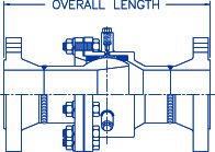
Type N Style II, III, and III-V Packed Ball Joints, 2-1/2″ to 48″ NPS
Information at a Glance
Series
6600 Hyspan Barco Ball Joints
![]()
Material
Steel
Size
1/2-48 in. / 12-1200 mm
Pressure
≤100, 150 & 300 PSI / 3, 10 & 20 Bar
Motion
unlimited
Canadian Registration
![]()
This product is registered throughout Canada under
CRN 0D9278.59870YTNADD3

Other Products
Product Description
Type N Style II, III & III-V ball joints combine the inner and outer seals that are common to all Hyspan Barco ball joints with injected graphite flakes with synthetic oil carrier, Grafoil® Flexible Graphite packing. This combination allows the use of a wide variety of high strength seal materials with the lubrication and high temperature sealing capability of Grafoil®.
Technology & Advantages
The ball sealing surface of Type N Style II, III, & III-V ball joints is protected with two mils of chrome plating consisting of one mil of hard chrome over one mil of crack 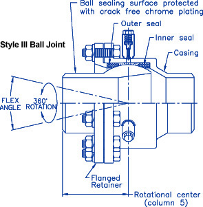 free chrome, and baked-on molybdenum disulfide lubricant coating.
Type N Style II ball joints can be repacked after installation in the system if necessary. Type N Style III and III-V ball joints can be repacked under pressure. All configurations can be completely disassembled for maintenance.
Type N Style II, III & III-V ball joints are used in steam and hot water distribution systems, chemical and petroleum plants, oil exploration drilling ships and platforms, and many other critical installations. All standard configurations are warranted for five years.
Higher pressure designs and designs conforming to the ASME code are available as Hyspan Barco ASME Class Ball Joints.
Type N Style III ball joints have been fire tested in accordance with API 6FA and approved by ABS Americas and Lloyd’s Register for shipboard applications.
Part Number
BB-41020 (Style II )
Part Numbers
BB-61020 (Style III)
BB-66020 (Style III-V)
Part Numbers BB-41533 (150 lb. Style II ) BB-41536 (300 lb. Style II )
Part Numbers BB-61533 (150 lb. Style III) BB-66533 (150 lb. Style III-V) BB-61536 (300 lb. Style III) BB-66536 (300 lb. Style III-V)
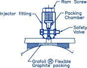
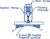
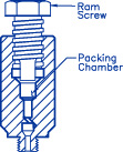
Style III-V Injector
Style III Injector
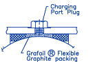
Style II Plugged Port
Design and Data

Flex torque is the moment (ft.-lbs.) at break-a-way to angularly displace a ball joint. Because the pressure thrust is reacted by the seals the flex torque is a function of pressure as illustrated by the adjacent graphs for Number 19, 21 and 39 seals.
The values given are for steam service. For water or oil service the torque values are 45% less.
Flex Torque
Type N Style II, III & III-V Ball Joints
Number 19, 21 & 39 Seals
Flex Torque Type N Style II, III & III-V Ball Joints Number 19, 21 & 39 Seals
Flex Torque Type N Style II, III & III-V Ball Joints Number 19, 21 & 39 Seals
Seal Number 19
Compound 19 is a pressure molded proprietary seal compound recommended for general purpose applications for steam, hot water and oil systems. Compound 19 has the highest pressure/temperature ratings of the available non-metallic seal materials.
Rated for service at temperatures from -50° F to 525° F.
Seal Number 21
Compound 21 seals are cast ductile iron and precision machined. The ductile iron combined with the chrome plated sealing surface of the ball provide a low friction long life seal.
Rated for service at temperatures from -20° F to 650° F with standard materials of construction.
Seal Number 39
Compound 39 seals are machined from Alloy 625 high nickel stainless steel. Alloy 625 has very high strength combined with exceptionally high corrosion resistance.
Number 39 seals are normally used in Type N packed ball joints made from special materials such as stainless steel and high chrome steel alloys. The temperature/pressure ratings are dependent on all of the materials used for construction .
Seal Number 45
Compound 45 seals are machined from ASME A-182 F11 chrome-moly steel forgings. Alloy F11 is a very high strength steel which can be used for higher temperature applications.
Number 45 seals are normally used in Type N packed ball joints made from special materials flange including high chrome steel alloys. The temperature/pressure ratings are dependent on all of the materials used for construction.
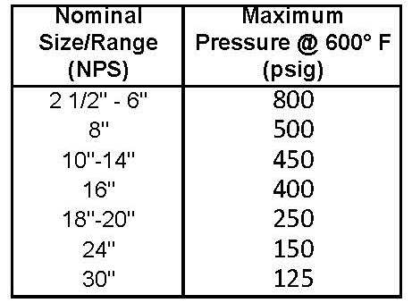
Pressure/Temperature Ratings Number 19 Composition Seal Type N Style II, III & III-V Weld End & 300 lb. Flanged
Pressure/Temperature Ratings Number 19 Composition Seal Type N Style II, III & III-V
150 lb. Flanged
Pressure/Temperature Ratings Number 21 Ductile Iron Seal Type N Style II, III & III-V Weld End
Style II Recharge Cylinder
Recharge Cylinder – Part Number 10-64416-43
Type N Style II ball joints are designed to be sealed after installation if a leak develops. A recharge cylinder that is designed to be temporarily installed in the charging ports is available.
Reload Kits – Part Number 10-64715-00
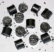
Recharge Kit Pellets
Flexible graphite packing material is available as pellets designed to be inserted into Type N Style II, III and III-V recharge cylinders. Each kit contains 13 pellets.
Insulation Covers
Removable, reusable insulation covers as specially made to fit all styles and configurations of Hyspan Barco ball joints. A full range of insulation and jacketing materials are available for all design temperatures. Covers for the Style III and III-V ball joints have pre-cut openings to allow access to recharge cylinders.
Installation and Maintenance Procedures
Installation Recommendations
- The media flow direction can be from either end of the ball joint except for liquids with suspended solids, then flow should be from ball end to casing end.
- In vertical installations, ball joints should be installed with the ball end down to prevent foreign matter from collecting between neck of ball and retainer
- Do not loosen the ball joint retainer during installation, or utilize ball joints as Unions.
Each joint is factory preset and tested before shipment. LOOSENING OF THE BALL JOINT RETAINER IS NOT RECOMMENDED. If the retainer must be loosened, loosen bolted retainers by loosening the bolting 1/4 revolution maximum using a standard crossing pattern. Retightened using the procedure outlined in Paragraph 7(j) of the Maintenance Instructions below. OW 1500 Style II ball joints have threaded retainers. Loosen the retainer 1/4 revolution maximum and retighten the same rotation. - Use CAUTION PREHEATING, WELDING, OR POST WELD HEAT-TREATING ball joints into the line. Excessive heating of the sealing area may cause leakage.
- Protect the exposed ball surface from weld splatter, and prevent dirt and debris from .
collecting around neck of ball. - Although ball joints can be rotated or twisted around the centerline, they are designed to absorb motion by the Offset Method that utilizes angular flex to provide the required movement. Consult a Hyspan Barco sales representative or contact Hyspan by email at websales@hyspan.com if an application involves extensive rotating motion.
Style II Recharge Cylinder
General Warning
Type N Style II, OW 1500 Style II and ASME Class Hyspan Barco Ball Joints are not designed for maintenance to be performed while the system is pressurized. DO NOT PERFORM ANY ADJUSTMENTS TO A BALL JOINT THAT IS PRESSURIZED.
Maintenance Instructions
To correct leaks or perform routine maintenance.
In order to repack Type N Style II, OW 1500 Style II and ASME Class Hyspan Barco Ball Joints a recharge cylinder (Part Number 10-64416-43) and packing pellets available in reload kits of 13 pellets (Part Number 10-64715-00) will be required. These products are available from an authorized Hyspan Barco representative or contact Hyspan at websales@hyspan.com.
- Relieve the internal pressure and allow ball joint to cool to a safe temperature for handling.
- Remove all of the charging port plugs.
- Prior to installing the recharge cylinder remove the ram screw and insert one (1) packing pellet. Replace the ram screw and rotate until a small amount of sealant has been forced out of the tip of the cylinder. Apply thread lubricant to recharge cylinder threads, and thread the recharge cylinder into the one of the ball joint ports.
- Inject sealant into the port by turning the ram screw until sealant is forced from the adjacent port. If necessary add additional packing pellets. Do not exceed 150 ft.-lbs of torque on the ram screw.
- Remove the recharge cylinder. Sealant should expand from the port. Replace the port plug.
- Thread the recharge cylinder into the adjacent port and repeat steps 5 and 6 until all of the ports have been charged and the plugs replaced. Be certain that all of the plugs have been replaced with the threads fully engaged and tightened prior to pressurizing. If leakage still occurs the ball joint can be disassembled for maintenance.
- TO DISASSEMBLE the ball joint for maintenance it must be removed from the system.
- Disassemble the joint by removing the retainer.
- Inspect the inner seal for wear: The inner seal is seldom worn enough to require replacement.
- Clean and inspect ball surface carefully. Replace the ball if it is worn, scored or pitted.
- Replacement balls, seals and packing are available from an authorized Hyspan Barco representative or contact Hyspan at websales@hyspan.com. Be certain to dispose of discarded seals and injected packing properly.
- To reassemble, coat the surfaces of the seal(s) and ball with a light coat of assembly lubricant. For service over 350º F use molybdenum disulfide based lubricant.
- If the inner seal has been removed, install it in the case with the concave surface out by tapping it in place evenly with a soft mallet.
- Slide new outer seal over extended end of ball with the concave surface mating to the convex surface of ball.
- Replace ball into casing.
- Tap the new outer seal evenly with plastic or rubber hammer into casing around ball.
- For bolted retainers tighten retainer bolting to the following factory torque settings using a standard crossing pattern.
| Number 11 Composition Seals | |
| Nominal Size(s) | Factory Torque (ft.-lbs.) |
| 2 1/2" & 3" | 12-15 |
| 4" through 6" | 40-50 |
| 8" through 30" | 80-90 |
| Number 21 Ductile Iron & Other Metal Seals | |
| Nominal Size(s) | Factory Torque (ft.-lbs.) |
| 2 1/2" | 6 |
| 3" & 4" | 10-12 |
| 5" & 6" | 14-16 |
| 8" through14" | 24-26 |
| 16" through 30" | 20-22 |
k. For the threaded retainer on OW 1500 ball joints add thread lubricant to the retainer threads and torque the retainer to 360 ft.-lbs.
l. Add the injected packing following Paragraphs 2 through 6 above. If possible perform an air and soap bubble leak test before reinstalling.
Installation Recommendations
- The media flow direction can be from either end of the ball joint except for liquids with suspended solids, then flow should be from ball end to casing end.
- In vertical installations, ball joints should be installed with the ball end down to prevent foreign matter from collecting between neck of ball and retainer.
- Do not loosen the ball joint retainer during installation, or utilize ball joints as Unions. Each joint is factory preset and tested before shipment. LOOSENING OF BALL JOINT RETAINER IS NOT RECOMMENDED. If the retainer must be loosened, loosen the bolting 1/4 revolution maximum using a standard crossing pattern. Retighten the bolting using the procedure outlined in Paragraph 6(j) of the Maintenance Instructions below.
- Use CAUTION PREHEATING, WELDING, OR POST WELD HEAT-TREATING ball joints into the line. Excessive heating of the sealing area may cause leakage.
- Protect the exposed ball surface from weld splatter, and prevent dirt and debris from collecting around neck of ball.
- Although ball joints can be rotated or twisted around the centerline, they are designed to absorb motion by the Offset Method that utilizes angular flex to provide the required movement. Consult a Hyspan Barco sales representative or contact Hyspan by email at websales@hyspan.com if an application involves extensive rotating motion.
General Warning
Type N Style III Hyspan Barco Ball Joints are designed for repacking to be performed while
the system is pressurized utilizing integral recharge cylinders. DO NOT PERFORM ANY ADJUSTMENTS TO THE RETAINER OF A BALL JOINT THAT IS PRESSURIZED. There are plugged ports between the recharge cylinders that are for factory use only – do not remove these plugs.
Maintenance Instructions
To correct leaks or to perform routine maintenance.
In order to repack Type N Style III Hyspan Barco Ball Joints packing pellets are required that
are available in reload kits of 13 pellets (Part Number 10-64715-00). Reload kits are available from an authorized Hyspan Barco representative or contact Hyspan at websales@hyspan.com).
1. Type N Style III ball joints are designed to be recharged by injecting packing under full line pressure provided the correct safety precautions are observed. Recharge only if a leak occurs. Only Hyspan packing material must be used. Recharging is accomplished by injecting packing through the recharging cylinders – DO NOT PERFORM ANY ADJUSTMENTS TO THE RETAINER OF A PRESSURIZED BALL JOINT. DO NOT RECHARGE WHILE PRESSURIZED IF LEAKAGE APPEARS THROUGH OR AROUND A RECHARGE CYLINDER.
WEAR EYE PROTECTION (FULL FACE MASK) AND PROPER SAFETY APPAREL.
2. Remove the ram screw from the recharge cylinder nearest the point of leakage.
3. Add lubricant (molybdenum disulfide based) to ram screw threads and insert one packing pellet in the chamber, and start ram screw.
4. Inject sealant into the port by turning the ram screw until it is bottomed against the cylinder. Do not exceed 250 ft.-lbs of torque on the ram screw.
5. Repeat Paragraphs 3 and 4 for the remaining recharge cylinders or until the leakage stops. Insert one pellet per cylinder. Repeat Paragraphs 3 and 4 one additional packing rotation or until leakage stops. If leakage still occurs the ball joint can be disassembled for maintenance.
6. TO DISASSEMBLE the ball joint for maintenance it must be removed from the system.
- Disassemble joint by removing the retainer.
- Inspect the inner seal for wear: The inner seal is seldom worn enough to require replacement.
- Clean and inspect ball surface carefully. Replace the ball if it is worn, scored or pitted.
- Replacement balls, seals and packing are available from an authorized Hyspan Barco representative or contact Hyspan at websales@hyspan.com. Be certain to dispose of discarded seals and injected packing properly.
- To reassemble, coat the surfaces of the seal(s) and ball with a light coat of assembly lubricant. For service over 350º F use molybdenum disulfide based lubricant.
- If the inner seal has been removed, install it in the case with the concave surface out by tapping it in place evenly with a soft mallet.
- Slide new outer seal over extended end of ball with the concave surface mating to the convex surface of ball.
- Replace ball into casing.
- Tap the new outer seal evenly with plastic or rubber hammer into casing around ball.
- For bolted retainers tighten retainer bolting to the following factory torque settings using a standard crossing pattern.
Number 11 Composition Seals Nominal Size(s) Factory Torque (ft.-lbs.) 2 1/2" & 3" 12-15 4" through 6" 40-50 8" through 30" 80-90 k. Number 21 Ductile Iron & Other Metal Seals: Add the packing following Paragraphs 2 through 6 above. Repeat the sequence until the packing no longer flows freely into the ball joint. If possible perform air and soap bubble leak test before reinstalling.
Installation Recommendations
Style III-V Recharge Cylinder
- The media flow direction can be from either end of the ball joint except for liquids with suspended solids, then flow should be from ball end to casing end.
- In vertical installations, ball joints should be installed with the ball end down to prevent foreign matter from collecting between neck of ball and retainer.
- Do not loosen ball joint retainer during installation, or utilize ball joints as Unions. Each joint is factory preset and tested before shipment. LOOSENING OF BALL JOINT RETAINERS IS NOT RECOMMENDED. If the retainer must be loosened, loosen the bolting 1/4 revolution maximum using a standard crossing pattern. Retighten the bolting using the procedure outlined in Paragraph 7(j) of the Maintenance Instructions below.
- Use CAUTION PREHEATING, WELDING, OR POST WELD HEAT-TREATING ball joints into the line. Excessive heating of the sealing area may cause leakage.
- Protect the exposed ball surface from weld splatter, and prevent dirt and debris from collecting around neck of ball.
- Although ball joints can be rotated or twisted around the centerline, they are designed to absorb motion by the Offset Method that utilizes angular flex to provide the required movement. Consult a Hyspan Barco sales representative or contact Hyspan by email at websales@hyspan.com if an application involves extensive rotating motion.
General Warning
Type N Style III-V and OW 1500 Style III-V Hyspan Barco Ball Joints are designed for repacking to be performed while the system is pressurized utilizing the integral recharge cylinders. DO NOT PERFORM ANY ADJUSTMENTS TO THE RETAINER OF A PRESSURIZED BALL JOINT. There are plugged ports between the recharge cylinders that are for factory use only – do not remove these plugs.
Maintenance Instructions
To correct leaks or to perform routine maintenance.
In order to repack Type N Style III-V and OW1500 Style III-V Hyspan Barco Ball Joints, packing pellets are required that are available in reload kits of 13 pellets (Part Number 10-64715-00). Reload kits are available from an authorized Hyspan Barco representative or contact Hyspan at websales@hyspan.com).
1. Type N Style III-V and OW 1500 Style III-V ball joints are designed to be recharged by injecting packing under full line pressure provided the correct safety precautions are observed. Recharge only if a leak occurs. Only Hyspan packing material must be used. Recharging is accomplished by injecting packing through the recharging cylinders – DO NOT PERFORM ANY ADJUSTMENTS TO THE RETAINER OF A PRESSURIZED BALL JOINT. DO NOT RECHARGE WHILE PRESSURIZED IF LEAKAGE APPEARS THROUGH OR AROUND A RECHARGE CYLINDER.
WEAR EYE PROTECTION (FACE MASK) AND PROPER SAFETY APPAREL.
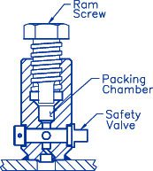
2. Select the recharge cylinder nearest the leak and rotate the 1/4 turn safety valve at the base of the cylinder to the off position (arrow is perpendicular to cylinder centerline).
3. Remove the ram screw from the recharge cylinder selected.
4. Add lubricant (molybdenum disulfide based) to ram screw threads and insert one packing pellet in the chamber and start ram screw two turns.
5. Open the valve (arrow is inline with cylinder centerline) and inject the sealant into the port by turning the ram screw until it is bottomed against the cylinder. Do not exceed 250 ft.-lbs of torque on the ram screw.
6. Repeat Paragraphs 3 through 5 for the remaining recharge cylinders or until the leakage stops. It leakage continues repeat Paragraphs 3 through 6 one additional packing rotation. If leakage still occurs the ball joint can be disassembled for maintenance.
7. TO DISASSEMBLE the ball joint for maintenance, the ball joint it must be removed from the system.
- Disassemble the joint by removing the retainer.
- Inspect the inner seal for wear: The inner seal is seldom worn enough to require replacement.
- Clean and inspect ball surface carefully. Replace the ball if it is worn, scored or pitted.
- Replacement balls, seals and packing are available from an authorized Hyspan Barco representative or contact Hyspan by email at websales@hyspan.com. Be certain to dispose of discarded seals and injected packing properly.
- To reassemble, coat the surfaces of the seal(s) and ball with a light coat of assembly lubricant. For service over 350º F use molybdenum disulfide based lubricant.
- If the inner seal has been removed, install it in the case with the concave surface out by tapping it in place evenly with a soft mallet.
- Slide new outer seal over the extended end of ball with the concave surface mating to the convex surface of ball.
- Replace ball into casing.
- Tap the new outer seal evenly with plastic or rubber hammer into casing around ball.
- For bolted retainers tighten retainer bolting to the following factory torque settings using a standard crossing pattern.
| Number 11 Composition Seals | |
| Nominal Size(s) | Factory Torque (ft.-lbs.) |
| 2 1/2" & 3" | 12-15 |
| 4" through 6" | 40-50 |
| 8" through 30" | 80-90 |
| Number 21 Ductile Iron & Other Metal Seals | |
| Nominal Size(s) | Factory Torque (ft.-lbs.) |
| 2 1/2" | 6 |
| 3" & 4" | 10-12 |
| 5" & 6" | 14-16 |
| 8" through14" | 24-26 |
| 16" through 30" | 20-22 |
k. For the threaded retainer on OW 1500 ball joints torque the retainer to 360 ft.-lbs.
l. Add the packing following Paragraphs 2 through 6 above. Repeat the sequence until the packing no longer flows freely into the ball joint. If possible perform air and soap bubble leak test before reinstalling.
Teflon® is a registered trademark of Dupont
Ordering Information
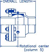
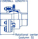
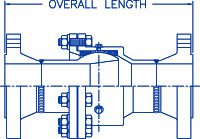
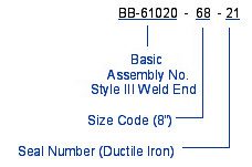 To order or specify Hyspan Barco Ball joints state the complete part number which includes; the basic Assembly Number selected from the illustrations, the Size Code from Column 2 of the Dimensional Data tabulation, and the Seal Code based on the seal material required.
![]()