
Series 7500 Formed Metal Bellows
Information at a Glance
Series
7500 Formed Metal Bellows
![]()
Material
Steel
Size
1/2 -48 in. / 12-1200 mm
Pressure
≤100, 150 & 300 PSI / 3, 10 & 20 Bar
Motion
unlimited
Product Description
Series 7500 formed bellows can be used in assemblies and for applications that are only limited by your imagination. Hyspan is ready to assist you from preliminary design to final testing. The company maintains extensive engineering capability for the design of metal bellows and related hardware, and has complete facilities for prototype production and development testing. Once developed Hyspan has unparalleled capability for volume production at company owned facilities at five locations.
Vacuum Applications
Series 7500 Bellows can be used for high-vacuum applications requiring leakage rates less than 1 x 10⁻¹⁰ STD ATM CC/SEC at base pressure of 1 x 10⁻⁶ TORR.
Since most of these applications require extremely flexible bellows, Hyspan recommends materials thickness of 0.006″ for inside diameters (I.D.) up to 4.5″, 0.008″for I.D. up to 8.0″, and 0.010″ for I.D. up to 14″. Any material Thickness can be used which has a maximum pressure (Column 7 on pages 6-17) exceeding 15 PSIG. Type 321 stainless steel is preferred because of its weldability and availability; however, other alloys can be substituted.
Weld attachments for high-vacuum applications are very critical. Because of the thin bellows material that is normally used, the addition of filler rod is not practical. The illustrations show the Hyspan recommended weld joints for internal and external attachments. The bellows must be a tight fit to the band, and the materials compatible because they are fused together.

Hyspan manufactures standard formed metal bellows configurations that are suitable for most applications. Inside diameters range from 1.0″ through 96.0″ with a wide range of material thicknesses, convoluted lengths and materials. Complete technical information is tabulated including design pressure, spring rates and cycle life.
Beryllium Copper
The beryllium copper alloys have high thermal and electrical conductivity similar to pure copper. It can be readily joined by resistance and fusion welding, brazing and soldering. The material is nonsparking, nonmagnetic; it has high galling resistance, and maintains its strength and ductility at cryogenic temperatures.

Valve Seals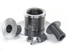
Formed bellows are commonly used for packless valve seals in safety, control and high vacuum valves. Hyspan has a complete library of designs for commonly used valves, and the capability to develop new designs. For high temperature and corrosive service specialty alloys such as Monel 400, Alloy 625, and Hastelloy C-276 are available.
Pressure Restrained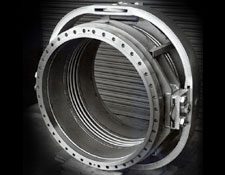
Structural components can be added to react the pressure thrust force of unrestrained bellows. In the photograph to the right, gimbal hardware has been added which restrains the bellows but allows universal angular motion. Two or three joints (depending on the application) of this design will absorb linear motion in all directions.
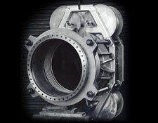
This photograph is an in-line pressure balanced assembly. There are four small diameter which have a total effective area equal to the larger line bellows, and through the rods and structure the pressure thrust is balanced internally. The only resistance to axial motion is the bellows axial spring rate.
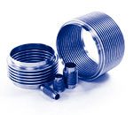
Wave Guides
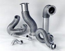 Formed bellows are used as wave guides. The assemblies in the photograph are made from aluminum. As shown they are easily formed into the required shape. Hyspan also manufactures bellows made from stainless steel and Beryllium copper.
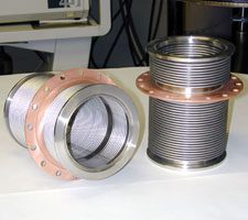
Cryogenics and High Vacuum
 Probably the most common applications of formed metal bellows are for cryogenic and ultra-high vacuum service. The assemblies shown in the photograph are for cryogenic service in medical equipment. The copper ring in the center is brazed to the stainless steel bellows. The completed assembly is leak tested to 1×10⁻¹⁰scc/sec. of helium. Hyspan maintains ASNT Level II helium leak testing certifications, and has facilities for liquid nitrogen testing.
Volume Compensation and Pressure Actuators
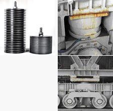 Bellows can be designed into sealed assemblies that can be pressurized internally or externally to provide large volume changes. The exposed bellows is a “crush formed” bellows assembly that was used in an electrical transformer that was designed for a 3x increase in length. The launch pads at Vandenburg AFB use this concept to raise and lower the launch vehicle. The design pressure for this application was 3000 psig.
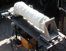
Development Testing
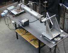 Hyspan has facilities and equipment for a wide range of testing that is required for bellows product development. The photographs illustrate two bellows designed into a “tied universal”. It was cycled with a lateral offset of 2″ each side of neutral for 22,000 cycles while pressurized to 280 psig and heated to 900°F. The forces and moments at the end attachments were measured during the test.
Bellows Nomenclature
Standard Tolerances
| Inside Diameter | Stock Number | Neck I.D. | Convolution I.D./O.D. | Convoluted Length | Trim Length |
| 1″-4″ | 7513-7544 | 0.01 | 0.03 | 0.06 | 0.03 |
| 4.125″-6″ | 7545-7557 | 0.01 | 0.04 | 0.06 | 0.03 |
| 6.25″-12″ | 7558-7577 | 0.02 | 0.06 | 0.09 | 0.06 |
| 12.25″-24″ | 7578-7586 | 0.03 | 0.09 | 0.12 | 0.09 |
| 26″-48″ | 7587-7598 | 0.06 | 0.12 | 0.12 | 0.09 |
| 50″-96″ | 7599-75110 | 0.12 | 0.18 | 0.18 | 0.12 |
Bellows Movement

AXIAL
Extension or compression from the manufactured length along the longitudinal centerline with ends parallel.

LATERAL
Displacement perpendicular to the longitudinal centerline with the ends parallel.

ANGULAR
Rotation of the longitudinal centerline about the perpendicular axis.

COMBINED
Axial, lateral, and angular movements can be combined within the rated movements.
TORSION OR TWISTING AROUND THE CENTERLINE
(Not recommended)
STANDARD TRIM
I.D. NECK
The neck and convolution I.D. are equal to the nominal I.D.

STYLE A
O.D. NECK
The neck O.D. is equal to the convolution O.D.

STYLE B
Expanded Neck
The neck I.D. or O.D. can be specified within the range of the I.D. to the convolution O.D.

STYLE C
O.D. Trim
The trim line is at the tangent point of the convolution O.D.

STYLE D
I.D. Trim
The trim line is at the tangent point of the convolution I.D.

INSIDE BAND

OUTSIDE BAND

Series 7500 bellows with standard, Style A, or Style B neck trims can be specified with inside or outside bands which increase the thickness from welding or added reinforcement. The band thickness is approximately 2.5 times the bellows thickness. The bands are attached by resistance seam welding for sizes 1″ through 48″ and by edge welding (GTAW) for larger sizes.
Caution: The use of bands is not recommended for vacuum applications requiring a mass spectrometer helium leak test.
Multiply or Laminated Bellows
Any Standard-size bellows can be fabricated with multiply construction up to four plies of equal thickness. The maximum pressure, spring rate, and stability pressure are increased in direct proportion to the number of plies, but with the same axial deflection as a single ply. Multiply design permits a lower spring rate and a greater cycle life than a single ply configuration for an equivalent pressure. This type of construction is recommended for applications with vibration or rapid cyclic movement of the plies.
Multiply construction is not recommended for vacuum application requiring a mass spectrometer helium lead test because of possible out-gassing from an undetectable lead in an inner ply.
Ordering Information
Hyspan Series 7500 Formed Bellows may be ordered directly from this catalog by using the stock number selected from the tabulation and adding the appropriate Dash Numbers.
If the neck trim length is deleted from the part number it is assumed to be the standard—0.75″ through 6″ I.D., 1.0″ over 6″ I.D. Optional materials, neck trim configurations, and bands must be specified separately—refer to pages 3 and 4 for options available.
Example
Size: 1.50″ I.D., 1.95″ O.D.
Material: .008″ Thick Type 321Stainless Steel
Convoluted Length: 4.0″
Neck Trim: 0.50″
Hyspan products are available from Sales Representatives and Distributors, or they can be purchased direct from the factory. The minimum factory order for open account customers, COD shipments, or bank card sales is $100.00 (USD). All major credit or debit cards are accepted. The minimum order for new account applicants is $100.00. Our Confidential Credit Application can be downloaded and forwarded to Hyspan for processing. All orders are subject to the following Terms and Conditions, and the above warranty applies to all material. Please read these documents.
![]() Confidential Credit Application (13.9 KB), can be completed on line.
Confidential Credit Application (13.9 KB), can be completed on line.
