Fluid Catalytic Cracking Unit Expansion Joints (FCC)
Product Description
The FCC process is one of the most important conversion processes in a petroleum refinery. The process converts high molecular weight hydrocarbon fractions of petroleum crude to more valuable products such as gasoline and olefinic gases.
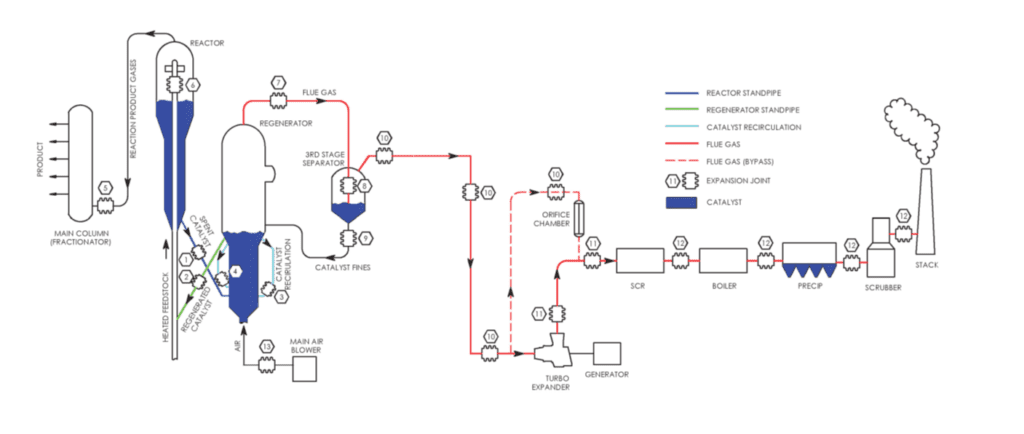
Due to the high temperatures throughout the FCC process, several expansion joints of various styles and configurations are required for the thermal growth of the high temperature piping.
The diagrams below show typical FCC processes; Catalyst, Energy Recovery, and Cleaning.
The table below shows type of expansion joint typically found in the high temperature piping between vessels or equipment.
Cold Wall Standpipe Expansion Joint with Pantograph Hardware
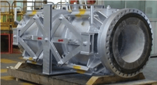
Cold wall expansion joints utilize a high density internal vibracast refractory lining to reduce the design temperature of the shell/piping below the temperature of the internal media.
Although the temperature of the catalyst or flue gas may be as high as 1,400 °F, the internal refractory lining reduces the shell temperature below 650 °F. As a result, carbon steel is usually specified for the piping material of a cold wall expansion joint.
Cold Wall Hinged Expansion Joint for Flue Gas Service (Cross Section View)
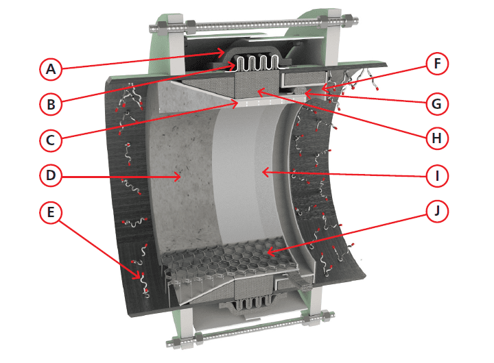
Design Features of a Cold Wall Expansion Joint
A. External Insulation: The external insulation elevates the bellows operating temperature above the internal dew point condensation temperature to minimize corrosion on the inner ply of the bellows. The external insulation can be temporarily removed during an outage to allow for inspection of the bellows element.
B. Two Ply Testable Bellows: See page 12 of this brochure for additional information on the two ply testable bellows.
C. Internal Flow Liner: The downstream end of the internal flow liner operates at the elevated temperature of the catalyst or flue gas, the internal flow liner is fabricated from T304H stainless steel. The upstream end of the liner contains a conical section to allow for the differential radial thermal growth between the “cold” upstream end of the liner and the “hot” downstream end of the liner.
D. Refractory: High density vibracast refractory insulates the inside of the piping to reduce heat transfer to the expansion joint shell.
E. Refractory Anchors: T304H stainless steel wavy vee anchors are used to anchor the high density vibracast refractory lining to the carbon steel shell.
F. Liner Gaps: Both the longitudinal and radial gaps at the open downstream end of the liner are sized for the design movements of the expansion joint. These gaps are minimized as much as possible to minimize the amount of catalyst that can enter the liner cavity.
G. Liner Seal: The liner seal minimizes the amount of catalyst entering the cavity between internal flow liner and the bellows. The liner seal also protects the structural integrity of the internal insulation.
H. Internal Insulation: The internal insulation reduces the bellows operating temperature below the creep temperature and prevents catalyst from packing in the cavity between the internal flow liner and the bellows.
I. Abrasion Lining: The cylindrical portion of the internal flow liner is packed with an abrasion resistant lining. It is reinforced by hex mesh (see below).
J. Hex Mesh: The inside of the internal flow liner contains a hex mesh lining. Hex mesh is used to anchor the abrasion lining and the refractory in the conical section of the flow liner.
Hot Wall Universal Gimbal Expansion Joint
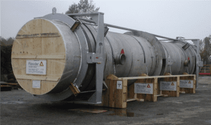
Hot Wall Single Gimbal Expansion Joint
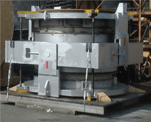
Hot wall expansion joints are commonly found in the flue gas piping throughout an FCC unit.
Hot wall expansion joints between the Regenerator and the 3rd stage separator are usually lined with hex mesh and a abrasion resistant lining to protect the piping from the catalyst fines in the flue gas. Hot wall expansion joints on the inlet and outlet piping of an expander are unlined to eliminate loose pieces of the abrasion resistant lining from traveling through the expander.
For both lined and unlined hot wall expansion joints, external insulation is installed around the piping of the expansion joint requiring the expansion joint piping be designed for the full temperature of the flue gas.
Hot Wall Expansion Joint for Flue Gas
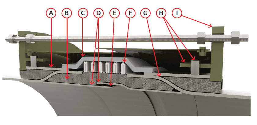
Design Features of a Hot Wall Expansion Joint
A. Shear Spool: The shear spool transfers the pressure thrust load, and any external design loads, from the external hardware to the line pipe.
B. Internal Insulation: The internal insulation reduces the bellows operating temperature below the creep temperature of the bellows material.
C. External Insulation: The external insulation elevates the bellows operating temperature above the internal dew point condensation temperature to minimize corrosion on the inner ply of the bellows. The external insulation can be temporarily removed during an outage to allow for inspection of the bellows element.
D. Internal Telescoping Flow Liners: The internal telescoping flow liners are a full bore design that reduces the pressure drop of the flue gas flowing through the expansion joint. The internal telescoping flow liners create a cavity for the internal insulation which is critical in reducing the bellows operating temperature.
E. Liner Gaps: The opening between the internal telescoping flow liners is located at the center of the bellows to minimize the radial gap needed for the movements of the expansion joint.
F. Two Ply Testable Bellows: See page 12 of this brochure for additional information on the two ply testable bellows.
G. Expanded Pipe: The smooth transition of the expanded line pipe minimizes the thermal stresses caused by the differential radial thermal growth between the line pipe operating at the full temperature of the media and the insulated bellows element operating at a reduced temperature.
H. Floating Ring Retaining Hardware: Pins welded to the outside of the shear spool slide thru corresponding holes in plates welded to the floating rings. These support the dead weight of the floating ring while allowing the differential radial growth between the hotter shear spool and the cooler floating ring.
I. Floating Ring: The floating ring is designed to restrain the pressure thrust load and any external design loads. The floating ring concept allows for differential thermal growth between the line pipe operating at the full temperature of the media and the insulated floating ring.
Due to insulation installed between the line pipe and the inside of the floating ring, the floating ring operates at a much lower temperature than the line pipe. In many cases the floating ring may be carbon steel even though the flue gas temperature may be 1,450 deg. F, carbon steel is commonly used for the floating ring due to the lower design temperature of the floating ring. The floating ring is not welded directly to the line pipe.
Expansion joint hardware is used in expansion joint applications to control movements and loads. Reference the table on pages 4 and 5 for locations where these types of hardware are typically utilized.
Gimbal
A single bellows gimbal expansion joint is shown at the left. The gimbal hardware allows the expansion joint to absorb angular movement in all planes. Like the hinge, the gimbal hardware is designed to restrain pressure thrust and other external loads. Gimbal expansion joints are used in pairs or in combination with a hinge expansion joint.
Single Gimbal Expansion Joint
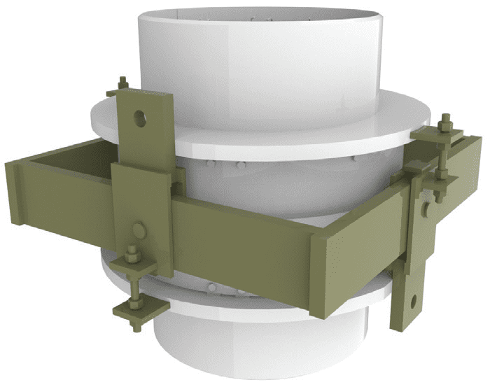
Universal Gimbal
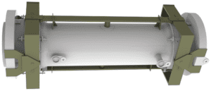
Hinge
A hinged single bellows expansion joint with limit rods is shown at the right. The hinge hardware allows the expansion joint to absorb angular movement in one plane. The hardware is designed to restrain pressure thrust and other external loads.
Single Hinged Expansion Joint
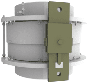
Limit Rods
Limit rods are used on many expansion joints to prevent the bellows from moving beyond the designed limit. In these applications the limit rods are not designed to restrain the pressure thrust load. Limit rods are shown in many of the designs on these pages.
Limit Rods
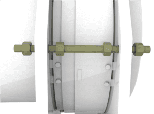
Pantograph linkages equalize the axial movement each bellows of a universal assembly. The gimbal pantograph expansion joint below left absorbs lateral deflection in two planes. The center gimbal ring allows the expansion joint to offset in the opposite plane to the pantograph without the linkage binding.
Gimbal Pantograpic Universal Expansion Joint
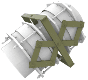
The pantograph linkage below allows for axial movement while supporting the dead weight of the refractory lined centerspool and the catalyst.
Elbow to Elbow Tied Universal Expansion Joint
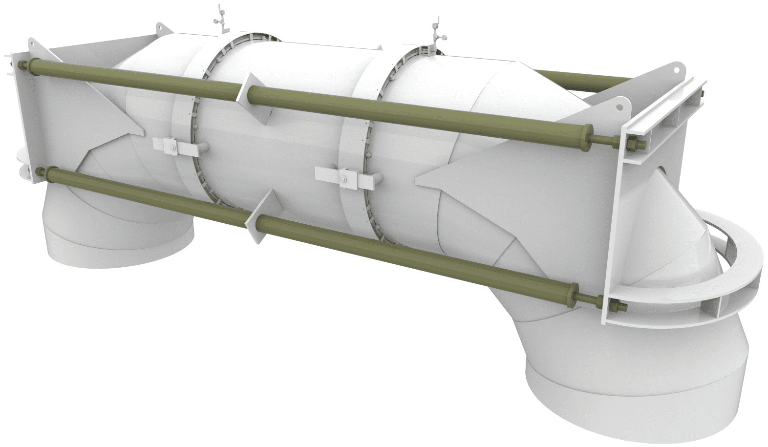
Tie rods are commonly utilized in universal expansion joint assemblies such as the elbow to elbow unit shown above. The expansion joint is capable of absorbing large lateral movements while the tie rods absorb the pressure thrust load.
The expansion joint bellows reliability is critical for FCC units as they generally stay on line for long periods of time between shutdowns. For this reason, bellows design incorporates a redundant pressure retaining ply combined with a leak detection hardware.
Oversize Clamshell Bellows
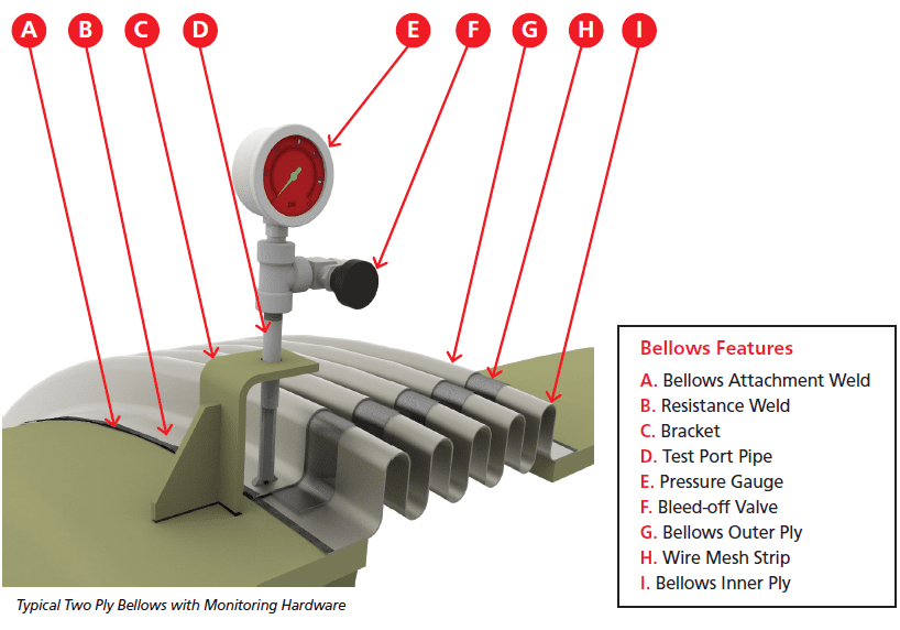
Two-Ply Testable Bellows
Typically the bellows is composed of two plies of a material that is capable of handling the full operating pressure alone. The inner ply retains the pressure under normal circumstances. If the inner ply develops a leak, the outer ply then retains the pressure. If this happens the pressure between the plies is ported to a gauge that will then indicate a reading. This alerts personnel to take precautions to repair or replace a failing bellows as soon as possible.
Oversize Clamshell Bellows
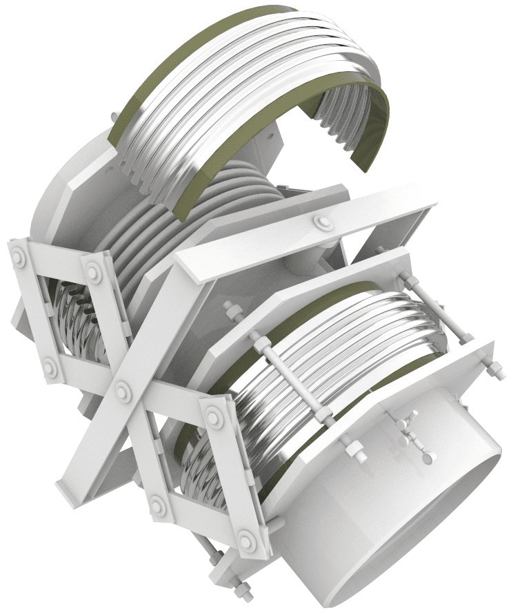
In the event of a bellows leak through both bellows plies it may be possible to install an oversize clamshell bellows over the existing bellows while the unit is on line. The bellows is supplied in 180 degree segments that are field welded 2 places along the longitudinal seam during installation. The bellows has a weld end that allows attachment to existing end plates.
The illustration below shows how a typical oversized clamshell bellows is installed in halves over an existing bellows. For a universal typically both expansion joints are covered at the same time to equalize the pressure thrust and spring rates.
Universal Pantograph Standpipe Expansion Joint
Ordering Information
Hyspan products are available from Sales Representatives and Distributors, or they can be purchased direct from the factory. The minimum factory order for open account customers, COD shipments, or bank card sales is $100.00 (USD). All major credit or debit cards are accepted. The minimum order for new account applicants is $100.00. Our Confidential Credit Application can be downloaded and forwarded to Hyspan for processing. All orders are subject to the following Terms and Conditions, and the above warranty applies to all material. Please read these documents.
Confidential Credit Application can be completed on line.

